
The Quartet.

 Multi-purpose receiver
Our multi-purpose laser receiver is suited for a wide range of acoustic and ultrasonic applications from the laboratory to the factory and available in the visible or infrared. Based on our patented multi-channel random quadrature detection technology, the system is designed for remote detection of sub-nanometer displacements. The system offers high sensitivity, requires low to no maintenance, can be fitted with a variety of laser wavelengths, and is capable of rapid scans and measurements. The Quartet was born of a research and development grant by NASA and the National Science Foundation.
FEATURES.
Robust & Versatile
Because the technology does not require control over the length of the optical path within the system, the Quartet is not subject to stability issues common to most long cavity and path-stabilized interferometers. It does not require high accuracy optical components or positioning, making it exceptionally rugged.
Fiberized Optical Head
A relatively small and versatile fiberized optical head is easily mounted to fit a variety of measurement conditions and can be set-up for a wide-range of stand-off distances. Its front lens can be easily changed or replaced if necessary.
Measurement Precision
The Quartet produces an analog signal that is proportional to surface displacement.
High Sensitivity on all Surface Types and Materials
Thanks to its multiple detectors and high transmission optics, the Quartet accomplishes efficient light collection and thus, high sensitivity. This continues to be true when the system is fitted with a moderately powerful laser thanks to low noise detectors and electronics. By detecting and processing many speckle interference signals, the Quartet achieves a stable demodulated signal even when processing a highly speckled beam. This means that it can perform measurements on any kind of surface, including rough, porous, rusted or mirror-like surfaces.
Inspection on Rapidly Moving Objects
Streamlined electronic processing allows the Quartet to perform single shot measurements on fast-moving objects, at speeds up to meters per second.
Not Wavelength Dependent
The Quartet can be fitted with a range of internal laser wavelengths ranging from visible to infrared.
Signal Indicators
Incorporated within the system are visual and audible signal indicators designed to help the user optimize their measurement setup. The Quartet also includes an internal calibration signal allowing for a calibrated output at 100mV per nanometer of displacement.
Beam Chopper (Optional Upgrade)
The beam chopper is an optional feature which allows the system to be used on materials with poor heat conductivity, such as plastics or carbon fiber materials without damaging the surface. A perforated disk synchronized with the generation laser “chops” the beam at a regular interval in order to prevent the sample from being exposed to continuous laser power. This feature does not affect the quality of the signal as it allows the laser to be used at full power, in contrast to alternative solutions such as using continuous but low laser power systems. Once installed, the chopper can be turned on and off to suit the application. This upgrade is compatible with new generation Quartets and is easily installed by replacing the top cover of the system.

SPECIFICATIONS.

Technology
Multi Channel Random Quadrature

Detection
Out-Of-Plane

Configuration
Optical Fiber

Internal Laser power
Up to 3W

Best NESD Value (out-of-plane motion)
2.10-6 nm/Hz1/2

Detection bandwidth
Up to 100MHz

Dimensions
160 x 300 x 330 mm3

Weight
9kg

Electrical requirements
110V / 220V
50Hz / 60Hz
TECHNOLOGY.
The Quartet receiver combines the advantages of homodyne interferometry with the benefits of multi-detector technology. The beam reflected by the sample’s rough surface is comprised of many speckles. The multi-speckled signal beam is combined with the reference beam and focused on 50 photo-detectors. Each detector collects a few speckles and delivers a homodyne signal.


Each homodyne signal is processed in parallel using a patented signal processing architecture. The signal processing is based on a “random quadrature” demodulation scheme which takes advantage of the random phase distribution inherent to speckle light.
More about Multi-Channel Random Quadrature
Rational
The idea behind Multi-Channel Random Quadrature was to devise a laser-ultrasound technology with a robust, compact design and a large depth-of-field capable of functioning effectively in a wide range of environments without loses in sensitivity, including on rough surfaces. With support from the National Science Foundation and NASA, we developed the Quartet. By collecting and processing a multitude of speckles, the Quartet is fully functional in environments which would otherwise be unsuitable for most other receivers and can perform measurements on all surface types — from mirror-like to rough surfaces.
Multi channel
Two detector arrays of 25 elements each allow the Quartet to collect more speckles than a standard receiver, which in turn translates to high sensitivity. To put it another way, employing MCQR technology is equivalent to using 50 Michelson interferometers in parallel.
The Quartet does not need to be stabilized as it relies on the random nature of speckles. Statistically, the speckle phase has a uniform distribution, meaning that it is 50% in-quadrature and 50% out-of-quadrature. The out-of-quadrature components don’t contribute to the signal, which is why we use 25 photodiodes on two detectors. Demodulation is required for both the in-phase and out-of-phase signals.

Optical Design
A laser beam generated by the internal laser passes through multiple optics within the receiver before being focused into a multimode fiber. At the end of the fiber, around 4-5% of the light is reflected back towards the receiver due to a natural optical phenomenon while the rest is focused onto the sample. The diffuse light reflected by the sample surface is collected by a large lens located at the front of the optical head, maximizing the quantity of speckles gathered for signal processing. The speckled beam then travels back through the optical fiber, interfering with the 4-5% partial reflection previously mentioned. It is important to note that the light polarization components are scrambled while traveling back through the multimode fiber. Once back in the system, the beam travels through a first Polarized Beam Splitter (PBS) which isolates the vertical polarization component and is in turn directed towards one of the two detector arrays. The rest of the beam travels through an Optical Isolator, which consists of a Faraday rotator and a PBS. This second PBS then sends the vertical (previously horizontal) component of the returning signal-beam back towards the second Multi-Channel Detector. Every signal from the photodiodes will be processed in parallel by an electronic demodulation.

Rectified demodulation
Because of the random nature of the phase of each of the 50 signals detected, the quartet is designed to perform signal rectification without consideration of phase. The streamlined electronic processing allows the Quartet to perform single shot measurements on fast-moving objects. Rectified Demodulation is also effective at rejection of background noise vibration.

Rectified Demodulation alone has a few downsides: it has a high-frequency and small-displacement limitation, and the direction of displacement is unknown. Therefore, the Quartet also uses Linear Demodulation.
Linear demodulation

Linear Demodulation is a similarly compact multi-channel architecture, but with a demodulation scheme that yields an output signal proportional to the wave-displacement. It is composed of a transimpedance followed by a logic control which detects the signal phase and switches between two summing amplifiers: one receives the in-phase and the other the out-of-phase signals. Lastly, both phases of the signal pass through a differential amplifier.


Multi-channel laser interferometric method and apparatus for detection of ultrasonic motion from a surface
Interferometric method and apparatus for linear detection of motion from a surface
Laser intensity noise rejection for interferometric apparatus
APPLICATIONS.
Our systems have a multitude of potential applications. Listed below are a just few brief descriptions of feasibility studies done using our receivers. If you have any questions regarding applications, we would be happy to lend our expertise to your problematic.
Non Destructive Evaluation on moving samples
Thanks to a short response time, the Quartet features the ability to perform highly sensitive measurements on moving samples. To demonstrate this capability, we performed experiments on a rotating disc composed of aluminum, 9 mm thick with a diameter of 130 mm. One side had a natural (reflective) finish while the other was sandblasted to create a uniform light-scattering surface.
The signal is first generated by a piezoelectric mirror continuously exiting at f=1.6MHz in the reference path. The signal amplitude is measured at 2f=3.2 MHz (Fig. 1A), because the rectification generates the second harmonic. There is almost no influence on the reflective side below 2 m/s, and then the signal drops slightly (about 5 dB) between 2 and 3 m/s. On the scattering surface, the signal begins 5dB lower than the reflective surface because less light is collected. The drop appears at a lower linear speed, but the signal is still detected. An example of pulse-echo LBU signals recorded with an offset between generation and detection is shown below.

B-scans were performed in a pulse-echo experiment on the scattering side with either the sample at rest or moving and scanning of the generation laser source. The linear speed at the point of detection was 2 m/s. The first three reflected P-waves were detected, as well as the surface wave, the first reflected shear wave and the converted wave (SP). This demonstrates the ability of the interferometer to process a signal even on rough,fast moving samples.

Non Destructive Evaluation on High-Temperature Ceramics

The time scale has been shifted, with t=0 corresponding to the arrival of the P-wave reflected through the thickness. The B-scan recorded by scanning the position of the generation line facilitates the identifications of the various waves. Below is shown the B-scans recorded at three different temperatures: 800, 1300 and 1500oC. The surface wave (R) as well as the reflected surface wave (RR), the direct compression wave (P-direct), the reflected compression wave (PP) and the reflected-converted wave (PS &SP) are clearly identifiable.

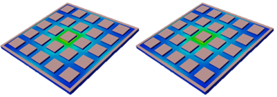
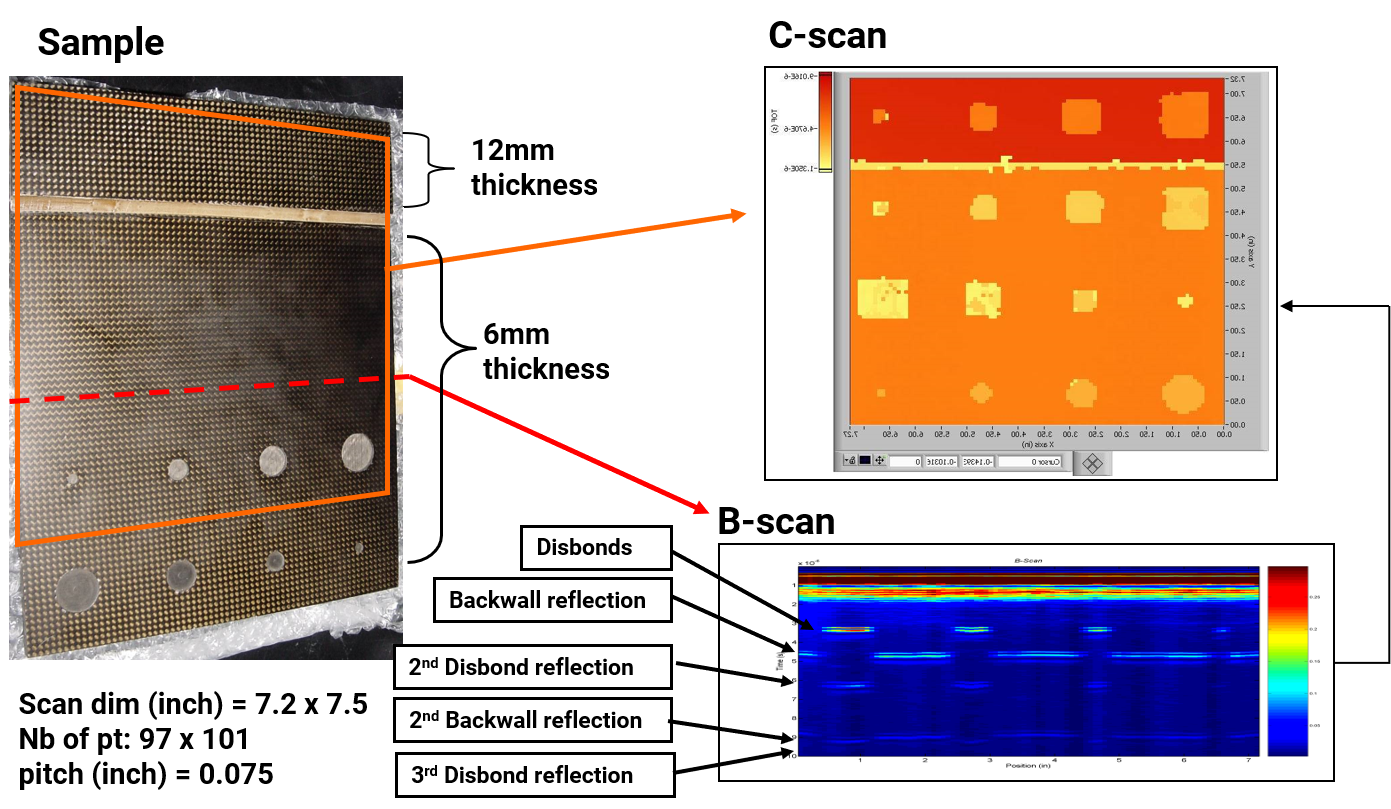
Detection of disbonds on composite materials
This experiment was carried out in a pulse echo configuration using the Quartet with rectified demodulation, a beam chopper and a generation laser on two composite layers bonded together. The goal was to detect disbonded areas between those two layers. Both B-scan and C-scan were realized. The B-scan below clearly shows the early arrival of the waves due to non bonding between the two layers. The C-scan was generated by displaying the time of arrival for the first echo.
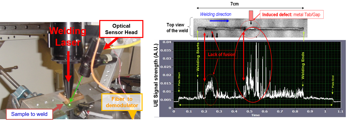
Ultrasonic Emission monitoring during laser welding
In-process monitoring of weld quality by continuous monitoring of the ultrasonic emission (UE) generated by the welding process during high-speed laser welding. In this case we want to evaluate the welding quality during high speed laser welding. We use the rectified demodulation and monitor the intensity of the ultrasonic emission generated by the welding process. As shown below, the intensity of UE clearly increases where defects appear.
Thickness measurement on cast iron samples
If the sonic velocity of the material is known, it is possible to measure the thickness of the specimen. Using a pulse-echo configuration (detection and generation on same side and superimposed), with the velocity of sound c and the time t between two peaks, the distance d in the material can be calculated. The following describes an experiment in which the Quartet, setup in a pulse-echo configuration, was used for thickness measurement on a cast iron sample. A scanning system was devised, composed of a Quartet and a generation laser and a translation stage. The Quartet with a detection bandwidth of 10 MHz was equipped with a 20 mW CW laser. A 200 mJ, Pulsed Nd:YAG laser set to 10nS pulse duration was used for generating ultrasounds, and was mounted to the translation stage allowing the generation beam to scan along a line with adjustable offset between generation and detection. The generation beam was focused to a circular spot with an approximate diameter of 2mm. Ultrasound generation was carried out in the ablation regime. The Geometry of the measurement appears as follows:

The samples used for the test were of thicknesses ranging between 3mm and 7mm. Measurements were carried out at room temperature. In the following B-scan measurement, the distance between generation and detection was from 22.5mm to 7.5mm. The P wave reflected through the thickness, PP wave, is clearly visible:

Seventy-five signals, corresponding to different offset between generation and detection were recorded. Each signal was recorded by averaging 16 laser shots at the same location. The P wave reflected through the thickness (PP wave), the surface wave (R wave) and the direct compression wave (P wave) are clearly visible. The processing software employed a coherent summation procedure to identify the wave arrival. Using the P wave velocity of 5.6mm/μs we calculated a corresponding thickness of 7.1mm at this location. With a caliper we measured at the same location a thickness of about 7mm to 7.2mm. However, it is important to note that the caliper measurement was only an approximation due to the roughness of the sample surface.
A second scan was carried out on the same sample, but this time with the generation and detection spots overlapping. The reflections of the P-wave through the thickness of the material are again clearly visible. During the first microsecond, the detector is blinded by the ablation blast. In this configuration, the shock wave (propagating in the air) that is generated during the generation by ablation is also visible. The size of the generation spot can be deduced from the location of the shock wave arrival. It corresponds in our experiment to a spot of about 2mm in diameter. The compression waves that have been reflected 1 time, 2 times and 3 times through the thickness are visible:

The graph below shows the averaged time signal with the generation spot centered on the detection spot. This averaged signal is the result of the summation of 15 signals corresponding to position between position 30 and 45 on the previous figure. The propagation time between 2 reflections, corresponding to a round-trip through the thickness, is 2.55μS. Using Vp=5.6mm/μs we calculate a corresponding thickness of 7.14mm at this location.

Rapid Scans on Complex Shapes
The following scan on a electrical ceramic high-power insulator was performed using the quartet integrated within a Tsukuba Technologies LUVI (Laser Ultrasonic Visualizing Inspector) solution. The setup allows for rapid scanning of a complex shape, while displaying the propagation of ultrasonic waves using a sophisticated visualization software. The LUVI detects at a pulsed generation beam at a fixed location and uses the reciprocity principle of sound propagation. Mirror scanning and a high-repetition rate laser enables high-speed inspection of an object with a complex shape, while visualization of ultrasonic waves makes identifying defect echoes easy.

In the clip below, the propagation of the ultrasonic wave is blocked by a crack and a reflected wave is subsequently generated
On-Line Inspection and Quality control
When propagating through a specimen, the ultrasonic waves carry information about the inner structure. Similarly, when propagating along a surface, the information about the surface quality and surface coatings can be extracted.