
The Tempo 1D.
")
 Ultra High Frequency receiver
The Tempo 1D is capable of detecting surface displacements resulting from the propagation of UHF ultrasounds, up to GHz. The system measures the spatial component normal to the surface of the target tested. It is used for characterization of micro and nano components. The TEMPO 1D is the result of 15 years of research, development and customer feedback. The system has become one of the most popular laser receiver worldwide for high frequency and ultra high frequency inspection.
FEATURES.
Ultra-High Frequency
The Tempo 1D can measure surface displacements resulting from the propagation of Ultra High Frequency ultrasounds, up to GHz.
High Efficiency Optical Design
The Tempo 1D is optimized to process highly speckled beams. It does not require a single speckle (reflection on mirror-like surface) like classical coherent laser ultrasonic receiver. It also includes a large, 2-inch aperture for high collection-efficiency, ensuring high sensitivity on light-scattering surfaces. The Tempo 1D exhibits high optical etendue.
Measurement Precision
The Tempo 1D produces an analog signal that is directly proportional to surface displacement at frequencies above a cutoff frequency.
Unaffected by Low Frequency Acoustic Noise
Performance is unaffected by low frequency acoustic noise caused by turbulence in the beam path (Below the cut-off frequency ~ 100Hz without compensation, and up to 10kHz with the internal compensation). The Tempo 1D has an integrated electronic feedback loop that compensates for low frequency acoustic noise up to 10 kHz.
Signal Indicators
Incorporated within the system are visual and audible signal indicators designed to help the user optimize their measurement setup. For absolute calibration, the Tempo 1D also includes an internal calibration signal and its output is autmoatically calibrated to 100mV for 1nm displacement.
SPECIFICATIONS.

Technology
Two-Wave mixing

Detection
Out-Of-Plane

Configuration
Free-Space

Internal Laser power
Up to 1.5 W @532nm

NESD (out-of-plane motion)
2.10-7 nm. (W/Hz)1/2

Detection bandwidth
Up to 1Ghz

Dimensions
492 x 302 x 114 mm3

Weight
16kg

Electrical requirements
110V / 220V
50Hz / 60Hz
TECHNOLOGY.
Two-Wave mixing in a photorefractive crystal
The Ultra high Frequency receiver is based on photorefractive two-wave mixing (TWM). A dynamic hologram resulting from the interferences between the reference beam and the signal beam is recorded in the photorefractive crystal. The diffraction of the reference beam by the dynamic hologram creates a local oscillator adapted to the signal i.e. same wavefront and same direction. Two-wave mixing in a photorefractive material is equivalent to an adaptive beam splitter. The two beams – signal and adapted local oscillator – are in perfect quadrature and are incident on the photodetector that delivers a homodyne signal.

High performances photorefractive crystals are used with reliable properties to insure an optimum two-wave mixing process. A high voltage field is applied on the photorefractive crystal in order to optimize the coupling and maintain the quadrature between the signal and the diffracted reference (adapted local oscillator). Photorefractive TWM has been extensively studied over the past 40 years and is a well-controlled process.
More about Two-Wave Mixing
Rational
The Two-Wave Mixing (TWM) approach offers the highest optical etendue of any laser ultrasonic technology. It can collect a great number of speckles, making it ideal for laboratory measurement on any surface type: polished or unpolished, flat or curve. When combined with a fast collection optic (F/2) a TWM interferometer allows for highly sensitive measurements on a wide-range of samples, including highly diffusive samples. The upper frequency limit of a TWM interferometer is defined by the bandwidth of the photodetector and can be chosen to be very high: up to GHz. There is therefore no upper frequency limit for the TWM process.
Optical Design
The internally generated laser beam is split into two: a probe beam and a reference beam. The probe beam travels through the system before coming into contact with the surface of the sample. From there, it is reflected back into the system. The reference beam never leaves the Tempo and is instead redirected towards a photorefractive crystal. In the photorefractive crystal (a Non-Linear Material), the two beams are combined, or mixed to create a dynamic hologram. If there is a perturbation at the surface of the sample, the system measures the phase variation between the reference and probe beams. This variation is then converted into an electrical signal by the photodetector. The response time of the process allows the Tempo to compensate for slow phase changes in the signal beam. The diffraction of the reference beam on the dynamic hologram creates a local oscillator adapted to the signal i.e. same wavefront and same direction. The two beams are incident on the detector. Two-wave mixing in a photorefractive material is equivalent to an adaptive beam splitter. It allows the Tempo to achieve perfect homodyne detection on a highly speckled beam.
When the surface of the work-piece or sample is displaced as a result of ultrasonic excitation, there is a transient phase change induced onto the signal beam. The coherent detection process converts this phase change into an amplitude change that is proportional to the phase change. To provide linear detection of the transient phase-modulated signal beam, the phases of the two combined beams must be biased in quadrature. In the Tempo, quadrature is achieved by the application of a high voltage dc electric field to the Photorefractive Crystal. The dc field also serves to enhance the strength of the real-time hologram.
APPLICATIONS.
Our systems have a multitude of potential applications. Listed below are a just few brief descriptions of feasibility studies done using our receivers. If you have any questions regarding applications, we would be happy to lend our expertise to your problematic.
Using laser interferometry to investigate strong multiple scattering of ultrasound near the Anderson transition in a three-dimensional “mesoglass”.
Research By: Eric Lee, John Page
Department of Physics and Astronomy, University of Manitoba, Winnipeg, MB, Canada R3T 2N2
In strong scattering media, the propagation of waves can often be described using the diffusion approximation. When the disorder increases, Anderson localization may occur. Scaling theory tells us that there is a transition from diffusive to localized behavior in three dimensional systems. This different behavior has been demonstrated by John Page’s group in similar samples. In the diffusive regime, the wave energy spreads out from the source point, but in the localized regime, the wave spreading is cut off and one can define the localization length from the width of the spatial profile.
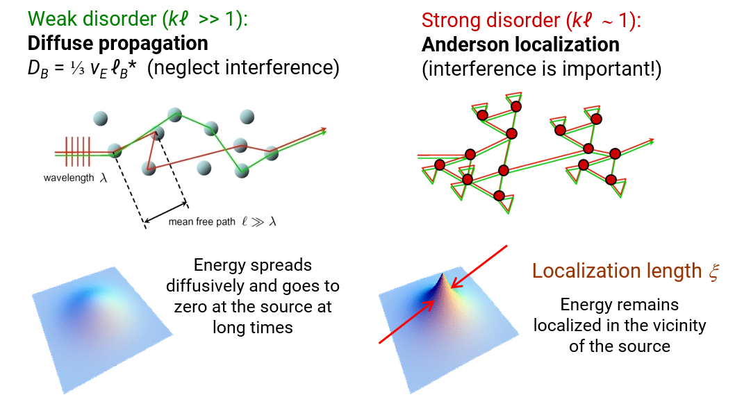
In the simplest case, the multiply scattered waves undergo random walks through the sample and energy transport is diffusive; then, the width of the spatial profile grows as the square root of time, and can be used to measure the wave diffusion coefficient. The best way of directly measuring this effect is to monitor the time dependence of the transverse width of the spatial profile on the sample surface opposite the source point.
The aluminum bead mesoglass samples are especially interesting physically because the disorder is so strong that instead of spreading diffusively without limit, the time dependent growth of the transverse profile is cut off by interference effects, and the waves remain trapped or localized inside a finite region of the sample centred near the source.
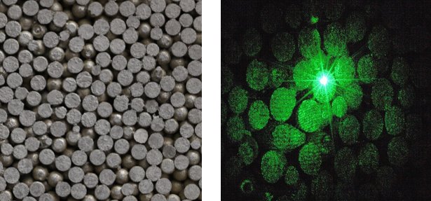
The sample is placed in air so there are virtually perfectly reflecting boundaries with a large acoustic mismatch. Luckily, this simplifies the theoretical interpretation. This plot shows typical data acquired when a short pulse of ultrasound is incident on the opposite side of the sample. Displacement near this red circle. The measured voltage from the laser interferometer can be converted to the actual displacement directly in a very convenient way. The normal displacements were measured over a 2 by 2 “ area with spatial resolution of 0.008”. The surface structure of the modal displacements is well-captured by the performed scan.
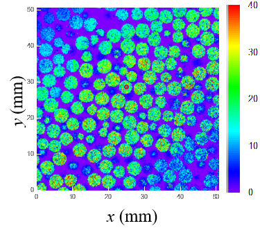
Here, the evolving field profile is visible. The spatial resolution of the scan is good enough to display the smooth variation of the field and the emerging field profile as a function of time is visible on the surface of the sample. The magnitude of FFT of the normal displacement at different frequencies is also shown.
Material characterization
Laser-ultrasonics are used to measure fundamental material properties such as the elastic modulus, shear modulus and Poisson ratio. Those parameters are of great importance for estimation of active stresses and life service

Acoustic emission
The laser receiver can also be used alone, without the generation laser, to listen to acoustic emission occurring when the sample is under stress.