
The Tempo 2D.

 Multi-component receiver
The multi-component laser receiver is capable of simultaneously measuring two components of the surface displacement, the out-of-plane and the in-plane motions, using a single laser probe and a single collecting optic. The detection of the in-plane component allows efficient detection of shear waves, particularly when the direction of ultrasounds propagation is normal to the surface of inspection. The TEMPO 2D was born of a research and development grant awarded by the National Science Foundation. The optical setup is based on the TEMPO 1D but with a customized linear array photo-detector capable of detecting both the in-plane and out-of-plane contributions of the surface displacement. The system is capable of reconstructing the complete ultrasonic field.
FEATURES.
Multi-Component Receiver
The Tempo 2D can simultaneously measure two components of the surface displacement — the out-of-plane and the in-plane motions — using a single laser probe and a single collecting optic at high frequencies with high sensitivity. The detection of the in-plane component allows for efficient detection of shear waves, particularly when the direction of ultrasounds propagation is normal to the surface of inspection.
High Efficiency Optical Design
The system is optimized to process highly speckled beams. It does not require a single speckle (reflection on mirror-like surface) like classical coherent laser ultrasonic receiver. It also includes a large, 2-inch aperture for high collection-efficiency, ensuring high sensitivity on light-scattering surfaces.
Measurement Precision The Tempo produces an analog signal that is directly proportional to surface displacements at frequencies above the cutoff. The 2D configuration of the system takes advantage of the
large optical etendue of the Tempo two-wave mixing technology to simultaneously measure in-plane and out-of-plane ultrasonic displacements. When measuring only the out-of-plane displacement, the 2D exhibits the same sensitivity than an optimized single-component interferometer. The in-plane component is obtained without reducing the sensitivity for the out-of-plane component.
Unaffected by Low Frequency Acoustic Noise
Performance is unaffected by low frequency acoustic noise caused by optical components or turbulence in the beam path (Below the cut-off frequency ~ 75Hz without compensation, and up to 10kHz with compensation). The Tempo 1D has an integrated electronic feedback loop that compensates for low frequency acoustic noise up to 10 kHz.
Signal Indicators
Incorporated within the system are visual and audible signal indicators designed to help the user optimize their measurement setup. For absolute calibration, the Tempo 2D also includes an internal calibration signal at 10 kHz.
SPECIFICATIONS.

Technology
Two-Wave mixing

Detection
In-Plane & Out-Of-Plane

Configuration
Free-Space

Internal Laser power
500mW @532nm

NESD
Out: 2.10-7 nm. (W/Hz)1/2
In: 1.10-6 nm. (W/Hz)1/2

Detection bandwidth
20MHz

Dimensions
492 x 302 x 114 mm3

Weight
16kg

Electrical requirements
110V / 220V
50Hz / 60Hz
TECHNOLOGY.
Multi-Component Detection
The Tempo is based on photorefractive two-wave mixing combined with a custom multi-detector, allowing for the detection of the complete ultrasonic field. The large collection angle of scattered light is divided in elementary angles Ɵi, which contributes to the ultrasonic field reconstruction. Each elementary angle carries phase information for both in-plane and out-of-plane contributions. The collected light is focused on a linear array of N elements using a vertical cylindrical lens

The signals are processed in pairs of the same incidence angle. For each pair, the two normalized signals are added to each other in order to obtain the elementary out-of-plane component, while their subtraction yields the elementary in-plane component.
More about multi-component detection
Rational
Simultaneous detection of two orthogonal components of the surface displacement is possible using two-wave mixing (TWM) combined with multi-channel detection. If ultrasounds are generated through the sample, multi components of the surface displacement can be measured using a single probe beam: the out-of-plane and in-plane components.
Optical Design
In a TWM based system the in-plane information is carried out by the speckles that are scattered away from the specular reflection. An interferometer with a large collecting aperture collects speckles corresponding to different angle of incidence.
An important feature of the Tempo systems is that multiple beams can be independently processed inside the same crystal without running into a cross-talk issue. This feature is used to realize a multiplexed interferometer for simultaneous detection of multiple beams corresponding to the observation at different viewing angles of the same illuminated point. The optical layout of the Tempo 1D is modified, such that the front collection optic is imaged on the detector and the single-element detector is replaced by a linear detector array.
Each element of the detector array corresponds to a small area of the back-scattered light entering through the front collecting optic and thus corresponds to light backscattered along well-defined incidence angles. Processing of the interference signals, as a function of the backscattered angle, simultaneously yields in-plane and out-of-plane displacements. The multi-detector is a linear-array consisting of 16 elements. The collected light is focused on the linear array using a cylindrical lens.
Backscattered light may not be uniformly distributed as it is affected by surface roughness. Therefore, each channel must be normalized before calculating the in-plane and out-of-plane components. This is achieved using automatic gain controlled (AGC) amplifiers which serve to monitor a low frequency calibration signal generated by an internal mirror mounted on a piezo-electric transducer in the path of the reference beam.
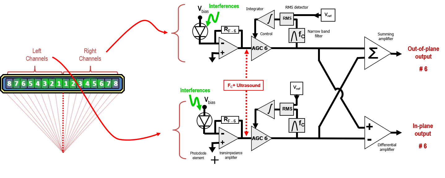
Following amplitude normalization, the signals are processed by pairs having the same incidence angles. For each pair, the normalized signals are added to generate the elementary out-of-plane component and their subtraction yields the elementary in-plane component.
However, the contribution in the final in-plane signal of each elementary in-plane component depends on the angle. A weight is thus applied, depending on the angular contribution of the in-plane for the elementary in-plane and for the out-of-plane components.
APPLICATIONS.
Our systems have a multitude of potential applications. Listed below are a just few brief descriptions of feasibility studies done using our receivers. If you have any questions regarding applications, we would be happy to lend our expertise to your problematic.
Detection of Through-Transmission Signal Generated by Thermoelastic Laser Pulses
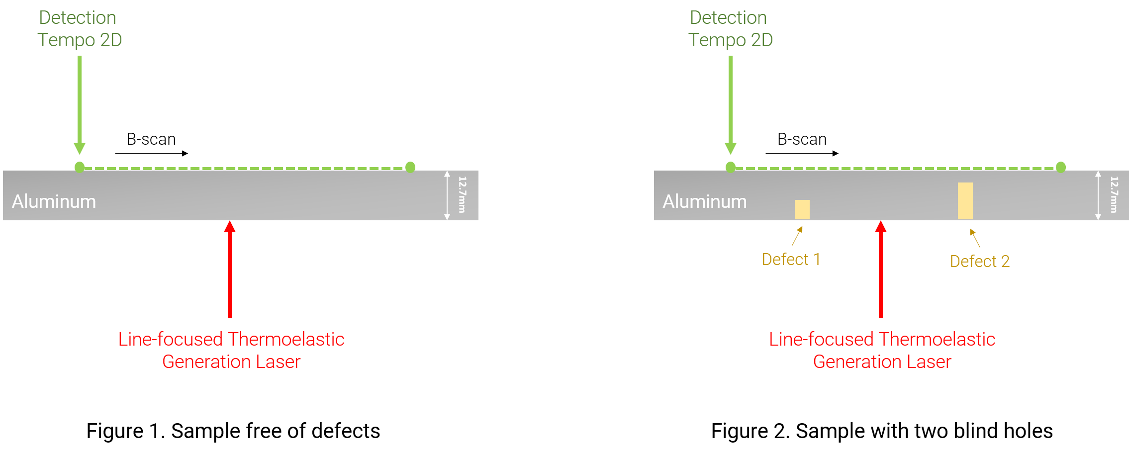
A through transmission experiment was carried out. Generation was achieved in a thermoelastic regime with a Nd:YAG pulsed laser. The generation laser beam was focused along a line with a cylindrical lens. The detection was carried out on the opposite side of the sample with a bandwidth between 20 kHz and 20 MHz. The sample was a 12.7 mm thick aluminum plate. The Tempo 2D scanned along a 50 mm line. In a first experiment (Figure 1.), we used a sample free of defects (no blind holes), while in the second (Figure 2.), two seperate blind holes were introduced.
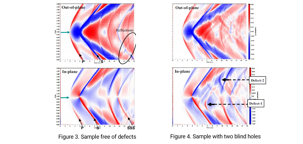
The B-scan results for both in-plane and out-of-plane displacements were recorded for both samples (Figure 3. and Figure 4.). The direct P-wave (P) and S-wave (S) arrivals at their respective arrival time 2 μs and 4 μs are clearly visible, along with multiple reflected and reflected/converted waves. As expected, the thermoelastic source generates a stronger S than P-wave. For these measurements, the calibration coefficient is 100mV/nm for both in-plane and out-of-plane outputs. After 12μs, some reflections from the sample edges are also visible on both in-plane and out-of-plane measurements. Moreover, as expected, the in-plane B-scan signal is asymmetrical around the epicenter, whereas the out-of-plane B-scan signal is symmetrical around the epicenter. In the second experiment, where two deffects where introduced, reflection / diffraction from the two defects are visible on both signals, but they are clearly identifiable on the in-plane B-scan.
Lamb Mode Resonance Measurement on Thin Plate
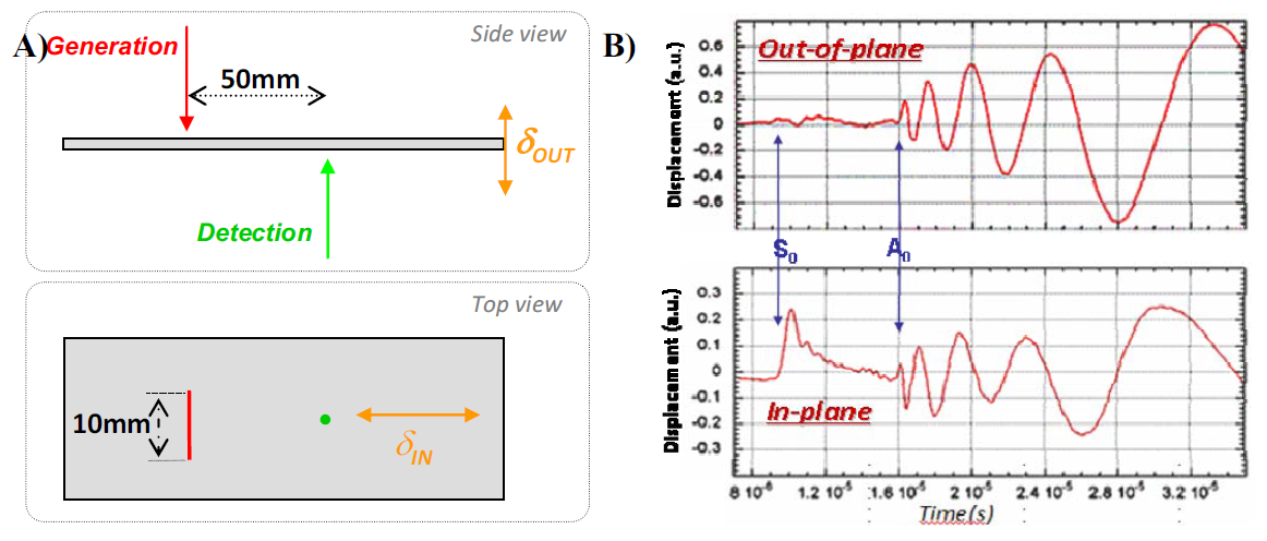
A through transmission experiment was performed. The sample is a 1 mm thick aluminum sheet. The generation was carried out with a line-focused pulsed laser beam. The measured in-plane direction is along the propagation direction. Figure 3-A illustrates low-frequency Lamb waves detected with the Tempo 2D after propagation along 50 mm. The detection bandwidth is [20kHz – 20MHz]. The signals were low-pass filtered with a cut-off frequency set at 1MHz, in order to only visualize the lower frequencies for the first set of measurements.
Figure 3-B describes the result of this experiment. The Lamb wave mode A0 is clearly visible after 16μs on both graphs. The S0 mode is clearly present on the in-plane signal, but hardly distinguishable on the out-of-plane. The graph enhances the fact that the symmetrical S0 mode has a stronger in-plane component which propagates faster than the asymmetrical A0 mode. Moreover, we can clearly see that the asymmetrical A0 carries more energy than the S0 mode. Finally, the A0 mode presents a phase shift of 90° between the in-plane and out-of-plane components, which justifies its asymmetrical property.
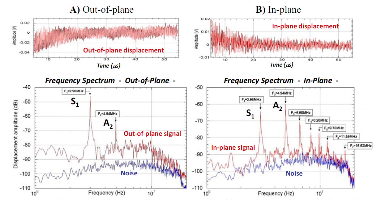
A second set of measurements is shown on Figure 4, with detection at the epicenter. Here the data are high-pass filtered, showing only the frequency above 1MHz.
Strong resonances are detected. Some Lamb modes exhibit an anomalous behavior at frequencies where the group velocity vanishes while the phase velocity remains finite. The zero-group velocity (ZGV) leads to sharp continuous resonance and ringing effect. Figure 4 shows the fast Fourier transform computed on the first 50μs of the signals. The spectrum of the out-of-plane signal (Figure 4-A) and the in-plane signal (Figure 4-B) clearly show the resonance of the S1 mode and of the A2 mode as described by Clorennec et al in their paper Laser Impulse Generation and Interferometer Detection of Zero Group Velocity Lamb Mode Resonance (Appl. Phys. Lett. 89, 2006). The resonance of the A2 Lamb mode corresponds to the thickness shear resonance (F_2.d=3.V_s/2), where VS is the shear wave velocity and d is the thickness.
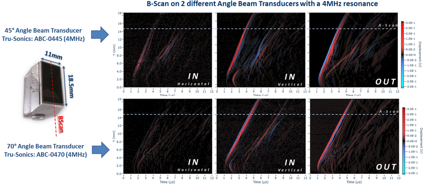
Transducer characterization
Measurements were carried out using 45° and 70° angle beam transducers, generating compressional waves with an angle relative to the surface of inspection. The interferometer is positioned in such a way that the outgoing laser beam is normal to the transducer surface of inspection, as shown here.

When propagating through a specimen, the ultrasonic waves carry information about the inner structure. Similarly, when propagating along a surface, the information about the surface quality and surface coatings can be extracted.
Bonding quality
Compressional waves can easily go through kissing bonds between two layers. The out-of-plane information therefore becomes insufficient to determine the quality of mechanical bonding. Due to motion perpendicular to the direction of propagation, the coupling of shear waves does not occur if there is no mechanical contact. The in-plane information is therefore used to determine the quality of bonding between two layers